Showing posts with label Blake Project. Show all posts

Friday, 23 March 2018

Easter Roundup

As is the way of academic term time - things have been fairly busy recently! As a result I have missed writing posts about several different project events, so here they are, amalgamated into a mega post:

Blake Project:

Yes, we finally handed it in, presented at an outreach event and semi-satisfied our supervisors. We managed to automate one of the cars, dictating it's behaviour with a learning state machine. This solution required us to quietly ignore that the 'learning' involved the car loosing control and falling from the track!

The final system did not include the brilliant perspex track, unfortunately I was not able to get the rails to be smooth enough to maintain reliable electrical contact with the cars as they travelled!

GrAVITAS:

I reckon that I will need to rename this project "The Han Solo Memorial" given how often it has gone into hibernation. Since the last post I discovered major potential instabilities in the planned circuit design, which scrapped the planned layout. Then University projects happened and we find ourselves a couple of months in the future.

Luckily I have now extensively tested new signal chain components (as a lucky byproduct of aforementioned University projects) which should mean that the hardware is put together very soon (fingers crossed)...

Robots: The Rock and A Hard Plaice, I and II

A bit more action here, mostly due to the fact that the Rock and a Hard Plaice suffered almost 50% fatalities per entry into a competition.

They were a blast to drive, not least because with two drivers the clusterbot became quite a sociable thing. Sadly weight saving measures left both bots rather vulnerable to more destructive opponents the first iteration of The Rock I fell victim to a vertical saw blade that discovered the only thing guarding The Rock's flammable lipo battery was a sheet of decorative paper!
Hmmm - I didn't intentionally add a fire weapon...
Of course, a video: https://www.youtube.com/watch?v=aL26JNXmnOE
(Destruction at 2 minutes 15 seconds)

Naturally once wasn't enough so I went about redesigning the cluster bot to be slightly better armoured, and actually used a 3d printer (splutter, splutter) to produce the chassis! Somewhat undaunted by the fact that I was greeted at the next competition by "are you going to explode again" from some very excited organisers The Rock and a Hard Plaice II managed to not die at all.
Sturdier, right...
The next thing to do was to go a step too far, which I managed to do admirably by entering a public antweight robot wars event.

(destruction occurs at around 10 mins 30 seconds)

I think the best bit was that I could find enough pieces to reconstruct the chassis and had to consolidate the available hardware into a single zombie-bot:

In retrospect the decision to add the 'Hard Plaice' picture to the underside was somewhat disturbing...
 Rubik's Cube Solver:

Perhaps the most enjoyable project I have ever taken part in, the Rubik's Cube Solver has also been one of the most time consuming!

In the past few months I have been able to design, build, redesign, rebuild and debug the communications hardware and software for sending information over the mandated audio cable.

For those interested m hardware consisted of a Sallen-Key filter designed with the Analogue Devices filter wizard (all praise the filter wizard) with non inverting amplifiers acting as input and output impedance buffers. The actual demodulation was done with an envelope detector circuit. Modulation was done with software driving a PC soundcard.

Amusingly today was supposed to be the have-everything-working day for the project with a presentation next term. However not a single group managed to hit the deadline, mainly due to integration issues, which meant that the unit director pushed the deadline back in an act of supreme benevolence! My group was 99.999999% of the way to hitting the deadline before we discovered some rather tricky bugs involving envelope detector fall of times (yes ... that was my section) which we were unable to both generate and integrate a solution for in time.

Given the state of things I am sure that I will be able to post a victory video shortly...
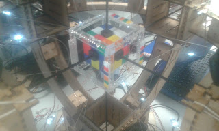
The initially planned communications tower, my demodulator fits into the second lowest box. 

Cube as it is now, with illuminating LED's and blackened actuation rods.

Satisfyingly not much has changed in the solver structure, except for the addition of a fluorescent-bulb-blocking shade. While it is not the most aesthetically pleasing structure coming together in the lab I am happy with it as the open frame and intentionally forgiving design has allowed us to test multiple system elements and interfaces well before full integration

The interior of the Demodulator box, I think the wiring leaves much to be desired!


Aaaand ..... there we go all caught up. With three weeks of holiday coming up either many more posts are about to be made, or my next post will be in a couple of months time after the next academic term!


Monday, 27 November 2017

Blake Project: all power to the engines!!

Just a quick post,

The Blake Project is to be presented on Friday, all or nothing, do or die - this is the final push!!!

UPDATE:

It worked, it actually worked! We had a few final system integration issues which meant that the Radar was the only thing that was properly presentable, however this seemed to work for our audience who I don't think would have enjoyed the autonomous car as much.
In a flash of madness I had laser cut some props to use on the day which meant we ended up pretending we had Darth Vader stopping cars travelling too fast (we had a silhouette of him and it kind of made sense) - segueing into a discussion of the radar if we found someone who was interested.

We now have another set of dates to have the project ready for presentation on, hopefully with a bit more success.

Sunday, 19 November 2017

One small glued joint for a student, a great leap for the Blake Project!

The Blake Project progresses. With pictures!

Work has been steadily progressing on the perspex track over the past month or so, but the past week has seen some major progress (not least because all lectures were suspended for a reading week). Because it was never going to be any other way, the first full completion of the track occurred this evening, just before the term resumes again. 

Shiny completed perspex track! (just imagine that the electrical tape holding the different sections together is not there)
 Why is this a 'first' completion?

  1. There is some trouble with the spacing between the rails at a couple of points. Unfortunately fixing this will probably require replacing the perspex of one of the straight sections.
  2. As seen in the photos the only satisfactory way to keep the track sections together at the moment is to use electrical tape - which is counterproductive in terms of making the race track look awesome. Ideally I would be able to glue all the sections together into one really large track piece. This might make the track difficult to handle and store so I will need to consult with the rest of the project team...
  3. Some of the pylons need to be moved around as they have been attached randomly at the moment with no thought for where the ones with extra attachment points should be so that the speed traps can use them.
These issues have to be addressed soonish, we have been asked to complete the project for 6th December by our supervisors, and many of the other project elements are now waiting on the track to be finished before they can start proper testing.

Therefore there is almost certainly going to be a 'victory' post in the near future! 

Until then ...

Atmosphere shot, same as when only the first two sections were complete, but now with the whole track!!

Hmm, I was going for more atmosphere - being able to see the top track from below - but all I can see is the mess of loose wires!

Thursday, 16 November 2017

When your problem is life ... and that infinitely repeating operation you programmed months ago

All right all right, I am the first to admit that in the grand scheme of things my programming ability is only slightly higher than that of a large twig.

However, my programs, in particular the growing gargantuan that is the Blake Project wireless network base station and autonomous car coordinator, do get to do some cool stuff.

The coolest of these is using my computer's full capacity. There is a certain joy in writing a program that takes so long to run that you can have a cup of tea while it executes ... if you ignore the fact that it is only relatively recently that this has stopped being a common occurrence, and that most of the delay is due to your inefficiency anyway. The Blake Project base station is a prime example of this pride's initial warm glow swiftly followed by agonising pain of n-degree noob programming burns.

In order to service both a GUI and several external serial links the base station implements multi-threading, executing multiple scripts 'at once' (not really it just fills in all the empty space that usually fills up a single thread of execution). While it means I get to use fancy terms like 'concurrent processing' when describing system behaviour, all this filling of idle operations also means that the CPU utilisation can get fairly high as well.

Unfortunately it got slightly too high as seen below, and the program started to lag.
Multithreading in python is only able to use a single processor core. We can see it maxing out the leftmost core until I swiftly kill it.
The primary reason for this was that one of the older threads had been allowed to request access to shared resources a quickly as it liked. This is BAD news, because it can ask as often as it wants (or can - if we have to insist that computers are inanimate), not getting the resource shortens the time the thread does other stuff for before asking again because what it was going to to do relies on the resource being given to it. Think annoying 'are we there yet' questions which are incessant until the answer is 'yes'.

The spoilt child analogy naturally develops when the thread's response to actually getting the resource is to look at it, see that nothing has changed since last time it looked (the data it was looking for only came through every now and then), and thus immediatly close the resource and release it for others to use.

Only to immediately ask for it back.

The solution is to teach everyone some manners, introducing delays into the loops of which the loops are a part, and re-enabling 'blocking' of the requests (pausing the program until it is successful, which reduces the number of requests enormously - there were good reasons for me disabling this I promise). This is going to have knock on effects later on which may or may not be irrecoverable, luckily that is for future me to work out.

Threads with manners, now using the CPU cores in a much more respectable manner. I don't actually know which one it is running on!
In fact, there is a large chance that that is what my next post shall be about, we'll have to see!

Tuesday, 14 November 2017

An Update

Silence for months must be followed with an update post, it is a rule of nature.

At the beginning of the (academic) year I listed some of the projects that I am working on at the moment. Question: how are they going? Answer: ummmmmmmmmm - I'll get back to you.

Immediately.

Blake Project:

Turns out not spending eight hours a day on a project can really slow progress. The AI has been semi constructed, the algorithm has been written, and so has the car driving code. All that remains is to plug it all together (which is always the longest part anyway!).

The track, is in pieces. Not as many pieces as it was, but it is many hours from completion. Luckily we have a reading week at the moment with many hours in it, many fingers are being crossed.

Its all there! Just not together.

 Telescope:

The updates that need doing have been identified, I really need to install a focussing mechanism better than a loo roll and friction. Also, upgrading the optical tube frame to be more portable, yet sturdier, is definitely on the cards at some point.

The telescope has had some good outings recently, trying but failing to see Uranus, getting a peek at Mars and a good look at the Orion nebula. I was going to try and point it at Jupiter and Venus on Tuesday, but the only place I could see them was from the middle of a road (I live in a city and they were close to the horizon), which I did not think was appropriate. They were awesome enough with the naked eye!

Solar Flare Detector:

Designed, the project decided to change the receiver to an SDR (software defined radio) based one, plugging the antenna (after a couple of filters and amplifiers) into a microphone slot and using a computer to do all the hard work. As it should.

Of course given that the solar flare detector should be running fairly constantly we have elected to use a Raspberry Pi as our enslaved processor - which means I have to relearn linux.

Also it got a name the GRand Assembly for Versatile Ionosphere Tracking and Astronomy of the Sun or GrAVITAS, a ripe source of puns, a source of gravitas (can't help myself), and of course an oblique reference to Iain M Banks. It looks very good in email headers.
The engineer at work, all four monitors in use. More screens = more work being done right?

Rubik's Cube Solver:

Good progress, but nothing of note yet. At least nothing worthy of photographing!


Lunar Rover Mk2:


Wow - got assigned to other projects within the space society for the moment, which was rather unexpected. The sneaky plan of the committee is to shuffle members around between projects as work amounts change. Ideally this means that some point in the future there will be much posting about rovers, the ideas coming out of the rover team so far are really rather cool.

Random Shiny stuff:

It always happens.

Robot Wars.

So the university electronics society run an ant-weight (150g, 10cm cube size limit) competition twice a year, so I should have seen this coming. Because this is going to be the fifth time we have entered, my team is going to attempt to build a cluster-bot, fitting multiple independent robots within the restrictions. This is leading to all sorts of fun and games trying to reduce the mass of the individual components of the robots which is likely to be the tricky bit.

This one also has a name, The Rock and a Hard Plaice, more details to come soon.

Who needs scales when you have string, water and a measuring jug?

Friday, 20 October 2017

New academic year == new projects

Another year of Uni has now begun, with the promise of a number of awesome projects to work on. This is not to say that the current work is going to be dropped, the Blake project in particular is continuing with the deadline of being complete by June next year.

However, the excitement always lies with the shiny new projects with all of the potential and none of the pragmatism (yet):

Being on the committee for the university's space society has meant that I was hoping to be able to push some electronics into the normal roster of rocket and rover projects. This push has resulted in the Solar Flare Detector being adopted as a project for this year. Consisting of a VLF radio receiver the end product will be able to track the sudden ionospheric disturbances that usually accompany flares hitting the Earth. Before you go and talk about us heading towards a solar minimum at the moment, which we are, there are still flares to be detected - just slightly smaller and less frequent flares. This project is currently starting up and already providing interest in the society from a broader range of subject disciplines, beyond the usual Aerospace Engineers.

The society is also re-entering the UKSEDS lunar rover competition after our successes last year (we came second), hoping to build on our design which ended up being decidedly improvised towards the end. It is likely the electronics are going to get a major overhaul but this should not be too hard given we now have experience.

Finally (for the moment) being the third year of the degree part of the assessment this year involves a group project. The aim of this project will be to produce a machine capable of solving a Rubik's cube. There are several restrictions that are going to add cool (and not obvious) electronics - I am sure that these will turn up in a future post.

Ongoing projects include the brilliant Blake Project, now cruising to completion - some sneakery is going to allow the accelerometer problem to be sidestepped, again I am sure that this will be written about somewhere else. The track itself is also slowly being completed - the workshop restocked perspex for the new term, and I immediately helped myself and spent a happy couple of hours producing all the parts needed.

At an even slower pace is the telescope, dredged from the depths of the blog. While I have really enjoyed using it so far there have been certain areas that either need improving or have already been improved. The mount (both tripod and pivot) have both been replaced with far more capable, but sadly not quite as DIY-y, elements. My range of eyepieces has also increased beyond a single dodgy 7.5mm plossl. Using the new setup I can clearly see all four stars in Mizar/Alcor, some awesome detail on the moon, the rings of Saturn e.c.t. However there is still more to do, I would like to 3D print an eyepiece holder and at some point I am going to need to replace the current optical tube frame.

All good things to look forward to, an hopefully write about!

A Summary:

Ongoing Projects:
    1. Blake Project (at a slower speed during the academic year)
    2. Telescope (gradually improving portability and stability)
New Projects:
    1. Solar Flare Detector (cooler acronym incoming)
    2. Rubik's Cube Solver (for degree)
    3. Lunar Rover Mk. 2. 

Monday, 11 September 2017

When your problem is life ... and statistics

We have been having slight issues with some elements of the race track system, today I decided to have a look at some of our problems using Matlab.

The issue is that there is a lot of noise in our accelerometer readings on the car. This makes distance and speed estimation rather tricky as errors are quickly accumulated and there is no easy way to get rid of them. So far we are implementing speed traps to try and give us defined locations and speeds for the car regularly.

While this does work, the autonomous car still has a tendency to floor the accelerator or brake at very odd points. I had a suspicion that these problems were arising from random noise in the acceleration readings, and set out to use Matlab to simulate a bunch of trials with lots of noise to see what the effect of this noise was.

For the simulations a constant acceleration of 1ms-2 had noise (normally or gaussian distributed with variance of 1) added to it. These acceleration readings were fed in to a set of equations mirroring those that run in the autonomous car and the distance/velocity predictions were recorded after a second. The beauty of using a computer like this is that (provided you have enough time) running a single trial is as easy as running 1000. For those interested the actual result of this test should be a final speed of 1ms and a final distance of 0.5m.

The results, surprise, surprise  seem to follow normal distributions:
Normally distributed with a mean close to the correct value, but an enormous spread of results.

Final velocity predictions were no better, although the mean was rather close
There are several things to note with this small experiment.

Firstly the noise in the acceleration readings was chosen at random, I will need more information from team members before I can make this more accurate. The noise profile is still plausible, if it is noise affecting our results chances are that it follows a normal distribution and a change in our readings of ~1ms is not impossible, given that we are reading from an analog accelerometer connected by long wires passing though an electrically noisy environment (with the car motor and track contact brushes).

Secondly, gaussian noise (the noise modeled) averages out to nothing if you wait long enough. Given how distance and velocity are calculated, this averaging out should be passed on to them in this particular scenario. Thus these two distributions are the best possible we might expect from our car. Ever.

This is a problem as much of the car's decision making relies on it having a good idea of where it is and how fast it is going, getting both of these bits of information wrong would explain some of the weird behaviour we have been seeing.

This is not a deadly problem, my next task will be to test some more complicated scenarios including varied acceleration and then work out a convolution I can use on the readings to try and give a more consistent result.

Until then!

Thursday, 7 September 2017

The Secret is Shiny-ness

With the Blake project nearing its end, one of the few major things left to do (apart from finalising and doing a final debug on everything) is to improve the look of the final product. Onward to many pictures, and then a bit of explanation:


The cars, a few versions after the last posted about. Now a full MDF chassis (which is a good thing?), removable side facades and a frame to allow for the easy mounting of electronic components. They have a really low track clearance so look hilarious going around corners.
A section of the new double layer track, construction still in progress. The track will be built mostly from clear perspex to make it look futuristic. It also has several functional purposes, the stacking of the two rails means we can have two track paths of equal length without resorting to a figure of eight design, making races fair while also keeping down the workload for the radar algorithms. It also ensures that our speed traps are only able to detect a specific car (the one on their rail), reducing their workload too.

The base station GUI in its start up state. It allows us to quickly change some of the track functionality (like turning the radar on and off), while also displaying some few properties of the system, such as which transmitting nodes have recently transmitted, and therefore whether they may have crashed. The black box at the bottom the window displays a log a all communications sent and received as the program operates useful for when trying to explain how our wireless network handles information.

This final push is mainly to improve the outreach value of the project, with three main aims.

Firstly we want to make the job of our presenters easier. By splitting up the different elements of the system, making them obviously discrete, the presenter will be able to walk through different parts of the system, and able to tailor their focus to the interests of their audience. For example, by adding a GUI to the base station we can remove the need for a demonstrator to start discussing the depths of the Python code, unless this is what their audience wants.

Secondly the final product needs to appeal to onlookers or even casual passers by, to make them curious about the track and its race cars. By making the track look awesome, hopefully we can provoke questions like: 'how does that bit work??', which is exactly what any presenter wants to hear as it allows them to jump straight into explanations and questions without having to focus to much on attracting people to talk to in the first place.

Finally we want to make the track and associated devices appear finished as an unfinished product will struggle to establish credibility for onlookers. This will ensure that potential audiences take the track and cars seriously and thus able to understand the elements of electrical and electronic engineering being displayed, rather than simply viewing it as a cool gadget thrown together but with no obvious value.

Hopefully when we are done in X units of time the project will end with something that can be used to help outreach for electrical and electronic engineering. While getting everything working is vital for doing this, improving the look of the final product is also necessary to be successful.

Tuesday, 22 August 2017

Collision avoidance testing: Is the radar up to the mark?

So after testing the radar's capabilities, I concluded two things. Firstly, the radar is certainly capable for collision avoidance at high speeds. Secondly, It's a pain in the butt to program at first. So, how did I come up with my first conclusion you may ask?

Well the company that produces these radars ( TI ) have made a Graphical User Interface to make what the radar outputs look pretty. The GUI gives us a visual of the radar capabilities like the X-Y scatter plot, which can accurately represent the location and coordinates of an object in front of the radar. Here is a video of the radar location system in action with the GUI in the bottom left!


As you can see, the car appears as a green dot whizzing around in a circular motion on the GUI. At times the car can appear as a group of closely-knit points due to the many possible reflective surfaces on the car (bonnet, doors, boot etc...). The radar is keeping up relatively well with the car as both the GUI and the actual car seem synchronised. It may not be perfectly accurate, but the radar is designed for much larger scale object thus it's doing remarkably well.

So the radar is pretty good at detecting an object move around at high speeds. Now how about a more realistic scenario. A reckless street racer called Dominic Toretto is participating in illegal racing activities for the thrill, fame and most importantly cash. He is notorious for his modified Mini Cooper.


Yes, OK ... not quite a muscle car, but it has enough power for a British version of Mr Toretto to wreak havoc on the streets. But what would happen if he was to approach a corner at high speed and have a sudden lapse of concentration? What would happen if he was too slow to brake and there were pedestrians on the pavement opposite him? Well, I'm sure you can answer than but this is where the radar comes in. Now if we model the radar as a pedestrian and an LED as the brakes of the car, we can see how it responds to such a scenario. If the LED at the bottom of the screen lights up as we cross the finish line, then its a job well done. At this point in the project I hadn't developed a suitable braking system for the car, but that is soon to come!


This slow motion video is perfect for seeing the exact location the car would brake. The LED goes high just before the car crosses the finishing line. This is important because at high speeds, the braking distance is much larger and so the car needs to stop sooner or it will skid off and cause damage.

So, the goal of this blog was to give you a visual of how we are testing the radar and how we might implement it in a demo for a university open day. A more technical blog on how the code is working and how I'm going to integrate a braking system with the radar will come soon. The key message here is that dangerous driving or a sudden lapse in concentration on the wheel can lead to life changing injuries or even death. I'm hoping that this piece of technology will be the norm for cars in the future to prevent such tragedies.

Friday, 18 August 2017

I do electronics on this project too, promise!

Another week, another four and a half days of programming followed by half a day of frantic CAD and laser cutter work.

Firstly, however, the not so photogenic stuff.

Following on from my development of code to run our radio modules I have taken on the task of organizing the wireless communication network of the track. Happily the hardware code mostly works now which has left me free to develop the base station, in Python (3.5)(hooray!!).

The base station will be used as a switching point for all transmitted data, interpreting, processing and redirecting messages. It will also have a graphical user interface (GUI) running on top of it for displaying data and allowing for us to send user commands (like 'start race' or 'deploy convenient obstacle'). The GUI will be written with TKInter, a lovely Python library that has the slight drawback that it can freeze up or take a long time to complete certain operations, at least when I use it.

This presents a major problem for the base station which ideally should be dealing with incoming messages as quickly as possible. The solution is to split the Python program up into multiple execution paths either through multi threading or multiprocessing (pretty much the same except that multiprocessing actually gets implemented as multiple programs running separately, while multi threading apparently runs as one process but using the idle times of one thread to run another). Concurrent programming is something I have wanted to do for a while as it opens up the full potential of whatever computer you happen to be running on and allows you to legitimately draw enormous flow charts with lots of arrows while bug fixing.

The test of truth at the end of the week was to run the multi-threaded base station prototype with a very basic graphical display. In the screen shot below you can see the results, I have a test transmitter spamming the base station with dummy data packets. The thread dealing with the interface between my wireless modules and the computer is receiving the data, dealing with it appropriately and then forwarding an appropriate message on to a nonsense location (the re-transmission is visible in the black dialog box). It is also sending messages to the thread running the graphical interface to provide some feedback.

The graphical interface thread it taking these messages and displaying them. It is also running a simple button 'Hi' which, when clicked, prints 'Hi' to the dialog box. You can see that the 'Hi' Message is being printed out at all sorts of places in the dialog, which I was using to prove that the treads were actually running separately .

The culmination of four days of intense python-ing 

Having tested this I then took most of Friday to design and build the first prototype of our final car chassis design. In the original project outline this was going to be 3D printed, but the laser cutter was available. No contest really.

This iteration of the has been designed to not need the origins scalextric chassis to mount onto and also to pack the electronics closer together as it is looking more certain that we will not be able to move everything over to our own custom printed circuit boards. I was also aiming to be able to mount the accelerometer above the track contacts (as this reduces the accelerations experienced by the car if it swerves) and provide attachment points for the cosmetic covering that will hopefully be added laster to make the car loop prettier.

As with the last design most of the work has been done with the laser cutter with only a bit of filing to correct some of my design errors. I did end up having to use perspex for the pivot mount as the MDF was unable to take the strain without breaking.

Now without the scalextric chassis! Still looks like a camper van.
Anyway, until next time!

Friday, 11 August 2017

Luxury Car Design (If you squint)

Following a week of more C programming I have spent most of today trying to help Valeriy with his accelerometer woes.

I must admit that watching him slowly get more and more desperate with his bug fixes has been rather amusing, but we have come to the conclusion that there are certain error sources that cannot be counteracted by software. The two big sources that we could deduce was excess electromagnetic noise from the car motor causing the accelerometer to act weirdly, and extra vibrations in the stack of electronics the accelerometer was attached to leading to the accelerometer experiencing accelerations on top of those experienced by the car.

My helpful contribution has been to design and build a superstructure to fit on top of the preexisting chassis with measures to reduce both of our sources of error. This involves creating a rigid structure to try and keep the accelerometer fixed relative to the chassis, and adding shielding to our two main sources of EM noise, the motor and contact brushes.


A quick session with the laser cutter later and I had most of my structure ready to be glued together ( I have decided that the laser cutter is by far my favorite tool up in the workshop, so quick, so precise and straight out of a spy movie). There was also a piece of scrap metal available of exactly the right width and thickness, so the metal plating was also fairly straightforward to make.

The result is not fancy, but it looks much cleaner than the mess of tape and haphazard stacking that it replaces and should definitely work as an initial solution to some of out problems.

The 'completed' superstructure. I think it looks a bit like a campervan!

MDF structural elements, laser cut

Metal plates to cut EM noise, at about 1 mm thick they are massively overkill as aluminium foil would likely do just as well. While cutting and measuring the pieces I was asked if I was building a tank!

Fully Autonomous Scalextric Racecar (10% of the time)

After a month of my teammates pestering me about this, it is finally time for me to write my first post here.😤


My main task has been to 'teach' the Scalextric car to drive around the track on its own. To realise this functionality I have used MSP430 LaunchPad (G2553 chip), DRV8848 motor driver booster pack and ADXL203 2-axis analogue accelerometer.

The whole system is powered from the rail of the track (~12V) with an on-board voltage regulator converting it 3.3V accepted by the LaunchPad.
First prototype
When it comes to Scalextric cars, most human drivers tend to keep the 'throttle' position constant, trying to keep the speed below the value at which the car will no longer be able to make the corners. However, there is a way to go faster: ideally, the car needs to accelerate at full power as soon as it exits a corner and then slow down to the critical cornering speed as late as possible before the next turn. It is hard for a human to control the 'throttle' quickly and precisely enough to make use of this technique but a computer program can do it, when supplied with the right data. The autonomous car has another, somewhat unfair advantage over a human driver: the motor driver chip is able switch the motor to induction braking mode and hence slow the car down more quickly. Pretty straightforward, right?

The program calibrates the internal acceleration values on start-up by assuming that the initial values given by the accelerometer correspond to zero-g. As the car starts in the beginning of the straight, the LaunchPad sets the duty cycle of the PWM signal fed to the motor to 100%. As the car moves along the track, the microcontroller calculates the car's velocity and coordinate from the accelerometer data and turns the motor off as soon as it reaches the pre-programmed braking point. It slows down to a safe cornering speed (which for the moment is also hard coded into the program) and keeps the PWM signal at the appropriate level so the car can make the corner. When the turn is complete and the lateral acceleration disappears, the car accelerates again and the cycle is repeated.

No matter how good the theory is, there are always additional challenges when the theory is applied in real life¯\_(ツ)_/¯. Any errors picked up by the accelerometer get accumulated and amplified when velocity and coordinate calculations are carried out making the resulting values unreliable. To prevent this, the program updates the coordinate based on the presence or absence of lateral acceleration. For example, when the car is on the back straight and the accelerometer detects large lateral acceleration, the program can safely assume that the car is entering the second turn (or turn 3 if you are a NASCAR fan). The coordinate value can be updated accordingly, as the positions of the ends of each straight are known (this project does not require the car to 'learn' the track).

To minimise the error in the velocity data, every time the car passes one of the 'checkpoints' (when the lateral acceleration appears or disappears), the program records the time elapsed since the last checkpoint and calculates the average speed of the car in the sector between the two checkpoints. As the speed in the corner is roughly constant, the average speed value determined using this method is close to the actual speed of the car at the exit of the corner and is certainly more reliable than the value calculated from the inertial measurements.

After converting all of the above into C code we get this:


There are still a few problems (not related to the frustrated engineer you can hear in the background): the program is visibly confused in the beginning, it takes a while for the car to realise it exited the corner and it starts braking in slightly different places along the straight every time, which eventually leads to a crash. The main cause of the problems is likely to be in the placement of the accelerometer: in the initial prototype it was mounted in the centre of the chassis, which meant that when the front of the car had entered a straight part of the track, the rear - and hence the accelerometer - was not aligned parallel to the track and was still experiencing lateral acceleration. The attachment was rather loose which could have been causing the accelerometer to shift its resting position relative to the chassis over time. In addition, the accelerometer was in close proximity to the motor and interference from it was affecting the readings. The imprecise readings led to significant errors in the coordinate calculations and the car was not able to predict its position accurately and consistently which in turn caused the car to miss the braking points.

With that said, we expect the performance of the system to improve significantly with the modifications to the structure planned: robust attachment of the ADXL203 on top of the front axle will improve the car's ability to detect the changes in lateral acceleration in time and - combined with some shielding - will protect the accelerometer from interference caused by the motor.

In case we don't get the accelerometer to work as precisely and reliably as we need, there is a backup plan. An IR LED/Detector pair near the end of each straight can be used to detect the car and contact it over the wireless link (the car and all the detectors will be equipped with the Anaren CC110L modules). The program running the car will know the ID and the corresponding coordinate of each detector, which will enable it to know its position - and therefore the braking point - more precisely.

Until then, as one of us likes to say, we need to let our subconscious to work on this problem😉.

Monday, 7 August 2017

The same, but different

Turns out that wireless communication is actually supposed to communicate information, rather than be used for somewhat dodgy range finding. (shock and horror)

Having spent a large portion of time on the latter use, it is now time for me to finally work out how to best use the former. While I have done the equivalent of 'hello world' during the RSSI measurements, I will now focus on maximizing the amount of useful data sent between transceivers. Initial testing of this meant simply hooking up a bunch of microcontroller units programmed to transmit random data as quickly as possible at a base station, and then reading the speed at which the data was being received by relaying it through a serial port to a waiting Python script.

A quick note, this method does mean that our speed measurements also include the speed at which information is being processed over the wired serial link, and some delays incurred by the software. I have deemed this to be acceptable, the wired serial link does not bottleneck the data flow, and other program delays are likely to mean that we get a data rate recorded that is closer to what will be achieved with the full system.

A quick Python session later and boom, I was recording data rate, with interesting results:
Program readout, showing a fairly stable data flow (such a relief after the instability of the RSSI readings!)
Unfortunately I realised that the receiving microcontroller was appending lots of information before relaying data down the serial link (like new line characters and RSSI measurements).

A quick C session later and boom, I was recording data rate with fewer pesky systematic errors in my results:
Program readout again, sadly the data rate dropped when we removed the extra characters
So, onward I must go, to either design a system capable of working within this data rate constriction, or find a way to boost the data rate of the transceiver modules.

A quick epilogue:

The Anaren Modules are actually quite sophisticated when they come to transmit, they will wait for the RF channel to clear before broadcasting and will limit the amount of time in for any given interval that they spend transmitting. While this may look like a prime target for removal when trying to boost data rate, this functionality is implemented for legal reasons (nobody likes a spectrum hoarder), and so is likely to remain.

Tuesday, 1 August 2017

The technology that could prevent road fatalities

With well over 1500 automobile related fatalities in the UK and over 35000 in the US, the road proves that it’s still a very dangerous medium of transport. While this number may never drop down to 0, it can still be reduced significantly. That’s where radar collision avoidance systems come in. These systems can detect when an object is too close to you at the speed you are travelling at and apply the brakes when necessary. Now of course I'm not saying that this gives you an excuse to drink drive or fall asleep at the wheel... This isn't a fully automated driving experience. But if you have a sudden lapse of concentrations at the wheel, it's more like a potential life saver. This is an area I will be investigating in my Blake Project.


The system of choice is the mmWave sensor system produce by TI called AWR1443. The sensor operates between 76-81GHz, which allows the transmission of electromagnetic waves with a wavelength of a few millimetres. The transmitted waves are frequency modulated continuous waves (FMCW). In short, their characteristics allow us to find distance, velocity and angle of the object in front. This process involves the waves being reflected by objects in the automobiles path and then being captured by the radar's receiving antennas. The time delay of the received signal can then be used to measure distance. The phase difference between the multiple received signals can be used to measure velocity.


So now that’s the technical jargon out the way, what makes it so brilliant? Well, due to the technology’s use of small wavelengths, it can provide sub-mm range accuracy. It can accurately distinguish between two objects that are in close proximity to each other. As a driver myself, it's always good to know the position of several cars around you in case they attempt a dangerous overtake or start drifting of into your lane. Also, it’s impervious to environmental conditions such as rain, fog, dust and snow allowing it to be used in pretty much any country’s climate. Furthermore, since the wavelengths being sent and received are millimetres long, the antenna are extremely small. This allows the radar's to be very compact in size and easily implemented along with the other embedded electronics in a car.


So a remarkable piece of technology indeed and one that’s still in its infancy. Due to this, the technology is rather expensive at the moment with one radar module costing $300. However, as the production methods develop and this technology becomes the norm, you can expect the prices to substantially decrease. Therefore, I will have a crack at implementing it in my Blake Project. I would like to TI's claims about the technology, albeit on a smaller scale.


I shall keep everyone posted on the progress!

Tuesday, 25 July 2017

The definitive duo of motor and micro controllers

So if you're wondering how one actually gets from writing code to physically moving motors then you've come to the write post! The combination of motor controllers and micro-controllers allows us to do such things.  Our motor controller is called the DRV-8848 BOOST. It's a brushed DC motor that can take a peak current of 2A and is therefore compatible with our motor. Also, it's a booster pack to the MSP430 MCU(Micro-controller Unit) which ensures compatibility and easy connectivity. But why are we using a motor controller in the first place? The current from the MSP430 is too small to drive a motor. So the motor controller acts as a current amplifier, feeding the motor a high current signal thus allowing it to spin.

The integrated chip on the MSP430 has to be programmed by the user, so it can provide us with some electronic sorcery called PWM (pulse width modulation). What is PWM you wonder? As the name suggests, the width of a pulse (which in this case is a square wave) is varied ,allowing us to vary the voltage at the output. Therefore, to increase the output voltage we have to increase the width (on-time) of the pulse. This makes PWM perfect for controlling power supplied to our DC motor.


So, the PWM signal is sent from the micro-controller to the motor controller, which is then outputted to the motor as revolutions. These revolutions translate to speed (revs per minute), thus the PWM voltage is proportional to speed. Therefore, by attaching the power rails to the motor inputs and connecting the motor and micro-controller up, we have a fully controlled motor. And what does all of this look like in the shell of a Mini Cooper Scalextric car you may be wondering?


Well.... we call it the monster mini! But do not be scared as we can significantly reduce the size by putting all this onto a custom PCB. Only time will tell. But for now its onto testing our beast.

Thanks for reading and until next time!


Woohoo, not C code!


Took a break from more wireless communication work today to put together a 'mk. 0' track piece for the Blake Project Scalextric track.

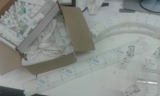
Having dismantled a corner section waiting for an software install last week, I attempted to remount the power rails into a track section of my own devising. The idea here is that we can reform the track and underlay to suit our own requirements (like adding space for wires or solar panels), make it slipperier (to make our AI look more professional), and increase the wow factor (by making it transparent, although this was a side effect of the acrylic sheet available today).

So a quick morning creating a CAD model (urgh, real objects ...) followed by a lengthier  afternoon with the laser cutter up in the engineering workshop, and I had my track section.

I do think that there will be future evolutions. The rails taken from the original scalextric track, while nice, are a pain to work with - I will try to come up with an alternative. Additionally I must have got my geometry wrong because the trusty file made several appearances!

On the other hand the track piece looks amazing, and could be made to be quite slippery. It also has lots of room for wires.

As you can see, it was only a mini piece.
Anyway, until next time!

More RSSI adventures

Some updates on the wireless system.

Having run a number of more trials of RSSI for distance in different conditions it is now obvious that RSSI is unlikely to be helpful over long ranges. I have included two graphs of my results, the first is of the raw data, which includes all measurements made (I took multiple for the same distance for almost all tests). The graph shows the general mess of values I was getting with very little correlation between distance and RSSI, especially when comparing results between tests.

This is evident in the second graph, which colour codes the results for the trail they were taken in. The most likely reason for these bizarre plots is reflections of the transmitted signal off of surrounding objects. This would explain why  the shape of the plots can vary so wildly between setting that the experiment was taken in, but remain fairly consistent for the same setting.  


The raw data, an enormous mess!

Results sorted by trial (with data averaged to ensure that there is only one point for each distance per trial). Clearly the devices surrounding affect the RSSI readings to a huge extent.
This is no problem for the project, it simply means that the RSSI readings are only effective over a short range. This can be easily counteracted by simply adding more receivers!

I just have to work out how to not clog up the airwaves...

Until next time!

Friday, 21 July 2017

A project - with fellow engineering students

So, three weeks into an outreach project and I decide to post about it (sounds like my usual behavior!).

The University has given two fellow electronic engineers and myself the chance to work on an eight week project over the summer, which is pretty cool. The purpose of this project is to bolster the outreach displays of the electronic engineering department with an exhibition of as many aspects of the discipline as possible. More simply, a scalextric track with autonomous cars, solar panels and radar, WOOHOO.

To be fair the past three weeks would have looked fairly unproductive to the casual observer, very few physical objects have come together. This is because the teams efforts have been directed towards learning how to use our micro controllers of (the University's) choice, the MSP430 manufactured by Texas Instruments.

While simple arduino-like interfaces exist for the MSP430, our project leader insisted that we mirror industrial practice more faithfully and use the more complex Code Composer Studio. While much of the past fortnight has been apparently fruitless as we began to understand how the interaction on the micro controller happened at a hardware level, as a team we now have a good understanding of the micro controllers at a hardware level (funny that).

My own part of the project so far has been focused on ensuring the cars do not collide, and that has mainly meant ensuring that they can communicate wirelessly. The idea behind this is that we can reuse the communicated signals to triangulate the positions of the cars via RSSI.

Having pushed my way up from register level code, today I was finally able to produce a signal strength for distance graph today!

the graph! note that I have no idea of the vertical scaling, hence the simple label, 'not dB'
Sadly the graph indicates that my job is only going to get more interesting from here on out, as clearly when I invert the axis to solve car positions I am going to end up with multiple solutions!

The graph also raises the question of the problem of signals being reflected and so on (at least some of the odd results recorded were unrepeatable after moving various items of equipment around). Finally the graph also reveals very odd behavior around 20 and 70 centimeters. While this most likely an inconvenient reflecting object, the dips correspond (if you squint) to one and two times the wavelength of the RF signal of around 34 cm.

This is going to be a long project so I am hoping to get most of the anomalies solved by next week when perhaps I shall have more to share.
A parting action shot, testing in progress!