Showing posts with label Laser Cutter. Show all posts

Friday, 23 March 2018

Easter Roundup

As is the way of academic term time - things have been fairly busy recently! As a result I have missed writing posts about several different project events, so here they are, amalgamated into a mega post:

Blake Project:

Yes, we finally handed it in, presented at an outreach event and semi-satisfied our supervisors. We managed to automate one of the cars, dictating it's behaviour with a learning state machine. This solution required us to quietly ignore that the 'learning' involved the car loosing control and falling from the track!

The final system did not include the brilliant perspex track, unfortunately I was not able to get the rails to be smooth enough to maintain reliable electrical contact with the cars as they travelled!

GrAVITAS:

I reckon that I will need to rename this project "The Han Solo Memorial" given how often it has gone into hibernation. Since the last post I discovered major potential instabilities in the planned circuit design, which scrapped the planned layout. Then University projects happened and we find ourselves a couple of months in the future.

Luckily I have now extensively tested new signal chain components (as a lucky byproduct of aforementioned University projects) which should mean that the hardware is put together very soon (fingers crossed)...

Robots: The Rock and A Hard Plaice, I and II

A bit more action here, mostly due to the fact that the Rock and a Hard Plaice suffered almost 50% fatalities per entry into a competition.

They were a blast to drive, not least because with two drivers the clusterbot became quite a sociable thing. Sadly weight saving measures left both bots rather vulnerable to more destructive opponents the first iteration of The Rock I fell victim to a vertical saw blade that discovered the only thing guarding The Rock's flammable lipo battery was a sheet of decorative paper!
Hmmm - I didn't intentionally add a fire weapon...
Of course, a video: https://www.youtube.com/watch?v=aL26JNXmnOE
(Destruction at 2 minutes 15 seconds)

Naturally once wasn't enough so I went about redesigning the cluster bot to be slightly better armoured, and actually used a 3d printer (splutter, splutter) to produce the chassis! Somewhat undaunted by the fact that I was greeted at the next competition by "are you going to explode again" from some very excited organisers The Rock and a Hard Plaice II managed to not die at all.
Sturdier, right...
The next thing to do was to go a step too far, which I managed to do admirably by entering a public antweight robot wars event.

(destruction occurs at around 10 mins 30 seconds)

I think the best bit was that I could find enough pieces to reconstruct the chassis and had to consolidate the available hardware into a single zombie-bot:

In retrospect the decision to add the 'Hard Plaice' picture to the underside was somewhat disturbing...
 Rubik's Cube Solver:

Perhaps the most enjoyable project I have ever taken part in, the Rubik's Cube Solver has also been one of the most time consuming!

In the past few months I have been able to design, build, redesign, rebuild and debug the communications hardware and software for sending information over the mandated audio cable.

For those interested m hardware consisted of a Sallen-Key filter designed with the Analogue Devices filter wizard (all praise the filter wizard) with non inverting amplifiers acting as input and output impedance buffers. The actual demodulation was done with an envelope detector circuit. Modulation was done with software driving a PC soundcard.

Amusingly today was supposed to be the have-everything-working day for the project with a presentation next term. However not a single group managed to hit the deadline, mainly due to integration issues, which meant that the unit director pushed the deadline back in an act of supreme benevolence! My group was 99.999999% of the way to hitting the deadline before we discovered some rather tricky bugs involving envelope detector fall of times (yes ... that was my section) which we were unable to both generate and integrate a solution for in time.

Given the state of things I am sure that I will be able to post a victory video shortly...
The initially planned communications tower, my demodulator fits into the second lowest box. 

Cube as it is now, with illuminating LED's and blackened actuation rods.

Satisfyingly not much has changed in the solver structure, except for the addition of a fluorescent-bulb-blocking shade. While it is not the most aesthetically pleasing structure coming together in the lab I am happy with it as the open frame and intentionally forgiving design has allowed us to test multiple system elements and interfaces well before full integration

The interior of the Demodulator box, I think the wiring leaves much to be desired!


Aaaand ..... there we go all caught up. With three weeks of holiday coming up either many more posts are about to be made, or my next post will be in a couple of months time after the next academic term!


Friday, 16 February 2018

Rubik's Cube ... Sphere

Hooray! Images from the Rubik's Cube project!

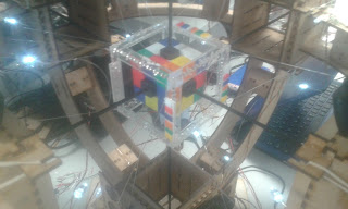
After many days of hard work from the team I am in we have finally completed the chassis for the solver, which will hold the cube, actuators and any electronics required. The idea when designing this chassis was to make the actuator mounts (these are the large empty boxes) as flexible as possible - meaning that we can build and test other subsystems (like cameras) before the motors and gearboxes are ready.

A quick note, this is my EEE degree's third year group project. Seeing that we are third years the project supervisor has decided to make things slightly harder - all communication to the chassis mounted electronics (and motors) has to be done via an audio cable, and we are not allowed programmable devices to decode the information from the cable. The team's solution to this involves a PC soundcard, lots of bandpass filters and a couple of basic ADCs to implement a simple analogue shift keying communication scheme with multiple sub channels separated in the frequency domain. The lack of programmable logic has left us having to control the actuating servos with one-hot logic, which slows down our solving speed considerably.
The cube sphere!
Three years of Engineering education put to good use in finding a way to hold the cube in place for camera testing. (Hot glue was also used)


Thursday, 18 January 2018

Telescope focuser

First post for the year is a surprise blast from the past: progress on the telescopes focuser - please try to hide that rolling of eyes.

So, almost a year after throwing the first bits of the telescope together I finally got into the mood to do some serious design work on the last major element of the telescope left - the eyepiece focuser.

Up until this point my eyepieces have been held in with friction and toilet rolls which is not to stable and does not allow for fine movements of the eyepiece. With the gradual upgrade in the other system components the focuser has finally become the weakest link.

A quick google search can show all sorts of brilliant designs - most of which have been made by someone else who is trying to sell them to you. Luckily there are also scattered articles of people making their own - generally with the a high level of ingenuity that most amateur telescope makers seem to possess by default.

In particular the ingenious Crayford focuser design, while used in high end commercial models, has been constructed in all sorts of ways including from assorted wood and plumbing scraps. That sounds like something I can do - especially when I have my trusty sidekick: Mr Laser-Cutter (its a double barrelled name).

I have just finished my CAD model ready for a workshop session sometime soon, which incidentally means I have pictures:

the focuser - note that my CAD skills are limited - I have not managed to put all my parts in an assembly to make the design look completely pretty.
The top view - hopefully the holes for the two bearing holders are visible on the left hand side of the image - the pressure will be applied with a spring pushing a pusher plate against the axle (which will happen on the right hand side of the image.

The pusher plate, I have tried to reduce its contact area with the rest of the focuser while maintaining its ability to stay straight by giving it the bowing in sides.


Sunday, 19 November 2017

One small glued joint for a student, a great leap for the Blake Project!

The Blake Project progresses. With pictures!

Work has been steadily progressing on the perspex track over the past month or so, but the past week has seen some major progress (not least because all lectures were suspended for a reading week). Because it was never going to be any other way, the first full completion of the track occurred this evening, just before the term resumes again. 

Shiny completed perspex track! (just imagine that the electrical tape holding the different sections together is not there)
 Why is this a 'first' completion?

  1. There is some trouble with the spacing between the rails at a couple of points. Unfortunately fixing this will probably require replacing the perspex of one of the straight sections.
  2. As seen in the photos the only satisfactory way to keep the track sections together at the moment is to use electrical tape - which is counterproductive in terms of making the race track look awesome. Ideally I would be able to glue all the sections together into one really large track piece. This might make the track difficult to handle and store so I will need to consult with the rest of the project team...
  3. Some of the pylons need to be moved around as they have been attached randomly at the moment with no thought for where the ones with extra attachment points should be so that the speed traps can use them.
These issues have to be addressed soonish, we have been asked to complete the project for 6th December by our supervisors, and many of the other project elements are now waiting on the track to be finished before they can start proper testing.

Therefore there is almost certainly going to be a 'victory' post in the near future! 

Until then ...

Atmosphere shot, same as when only the first two sections were complete, but now with the whole track!!

Hmm, I was going for more atmosphere - being able to see the top track from below - but all I can see is the mess of loose wires!

Tuesday, 14 November 2017

An Update

Silence for months must be followed with an update post, it is a rule of nature.

At the beginning of the (academic) year I listed some of the projects that I am working on at the moment. Question: how are they going? Answer: ummmmmmmmmm - I'll get back to you.

Immediately.

Blake Project:

Turns out not spending eight hours a day on a project can really slow progress. The AI has been semi constructed, the algorithm has been written, and so has the car driving code. All that remains is to plug it all together (which is always the longest part anyway!).

The track, is in pieces. Not as many pieces as it was, but it is many hours from completion. Luckily we have a reading week at the moment with many hours in it, many fingers are being crossed.

Its all there! Just not together.

 Telescope:

The updates that need doing have been identified, I really need to install a focussing mechanism better than a loo roll and friction. Also, upgrading the optical tube frame to be more portable, yet sturdier, is definitely on the cards at some point.

The telescope has had some good outings recently, trying but failing to see Uranus, getting a peek at Mars and a good look at the Orion nebula. I was going to try and point it at Jupiter and Venus on Tuesday, but the only place I could see them was from the middle of a road (I live in a city and they were close to the horizon), which I did not think was appropriate. They were awesome enough with the naked eye!

Solar Flare Detector:

Designed, the project decided to change the receiver to an SDR (software defined radio) based one, plugging the antenna (after a couple of filters and amplifiers) into a microphone slot and using a computer to do all the hard work. As it should.

Of course given that the solar flare detector should be running fairly constantly we have elected to use a Raspberry Pi as our enslaved processor - which means I have to relearn linux.

Also it got a name the GRand Assembly for Versatile Ionosphere Tracking and Astronomy of the Sun or GrAVITAS, a ripe source of puns, a source of gravitas (can't help myself), and of course an oblique reference to Iain M Banks. It looks very good in email headers.
The engineer at work, all four monitors in use. More screens = more work being done right?

Rubik's Cube Solver:

Good progress, but nothing of note yet. At least nothing worthy of photographing!


Lunar Rover Mk2:


Wow - got assigned to other projects within the space society for the moment, which was rather unexpected. The sneaky plan of the committee is to shuffle members around between projects as work amounts change. Ideally this means that some point in the future there will be much posting about rovers, the ideas coming out of the rover team so far are really rather cool.

Random Shiny stuff:

It always happens.

Robot Wars.

So the university electronics society run an ant-weight (150g, 10cm cube size limit) competition twice a year, so I should have seen this coming. Because this is going to be the fifth time we have entered, my team is going to attempt to build a cluster-bot, fitting multiple independent robots within the restrictions. This is leading to all sorts of fun and games trying to reduce the mass of the individual components of the robots which is likely to be the tricky bit.

This one also has a name, The Rock and a Hard Plaice, more details to come soon.

Who needs scales when you have string, water and a measuring jug?

Friday, 18 August 2017

I do electronics on this project too, promise!

Another week, another four and a half days of programming followed by half a day of frantic CAD and laser cutter work.

Firstly, however, the not so photogenic stuff.

Following on from my development of code to run our radio modules I have taken on the task of organizing the wireless communication network of the track. Happily the hardware code mostly works now which has left me free to develop the base station, in Python (3.5)(hooray!!).

The base station will be used as a switching point for all transmitted data, interpreting, processing and redirecting messages. It will also have a graphical user interface (GUI) running on top of it for displaying data and allowing for us to send user commands (like 'start race' or 'deploy convenient obstacle'). The GUI will be written with TKInter, a lovely Python library that has the slight drawback that it can freeze up or take a long time to complete certain operations, at least when I use it.

This presents a major problem for the base station which ideally should be dealing with incoming messages as quickly as possible. The solution is to split the Python program up into multiple execution paths either through multi threading or multiprocessing (pretty much the same except that multiprocessing actually gets implemented as multiple programs running separately, while multi threading apparently runs as one process but using the idle times of one thread to run another). Concurrent programming is something I have wanted to do for a while as it opens up the full potential of whatever computer you happen to be running on and allows you to legitimately draw enormous flow charts with lots of arrows while bug fixing.

The test of truth at the end of the week was to run the multi-threaded base station prototype with a very basic graphical display. In the screen shot below you can see the results, I have a test transmitter spamming the base station with dummy data packets. The thread dealing with the interface between my wireless modules and the computer is receiving the data, dealing with it appropriately and then forwarding an appropriate message on to a nonsense location (the re-transmission is visible in the black dialog box). It is also sending messages to the thread running the graphical interface to provide some feedback.

The graphical interface thread it taking these messages and displaying them. It is also running a simple button 'Hi' which, when clicked, prints 'Hi' to the dialog box. You can see that the 'Hi' Message is being printed out at all sorts of places in the dialog, which I was using to prove that the treads were actually running separately .

The culmination of four days of intense python-ing 

Having tested this I then took most of Friday to design and build the first prototype of our final car chassis design. In the original project outline this was going to be 3D printed, but the laser cutter was available. No contest really.

This iteration of the has been designed to not need the origins scalextric chassis to mount onto and also to pack the electronics closer together as it is looking more certain that we will not be able to move everything over to our own custom printed circuit boards. I was also aiming to be able to mount the accelerometer above the track contacts (as this reduces the accelerations experienced by the car if it swerves) and provide attachment points for the cosmetic covering that will hopefully be added laster to make the car loop prettier.

As with the last design most of the work has been done with the laser cutter with only a bit of filing to correct some of my design errors. I did end up having to use perspex for the pivot mount as the MDF was unable to take the strain without breaking.

Now without the scalextric chassis! Still looks like a camper van.
Anyway, until next time!

Friday, 11 August 2017

Luxury Car Design (If you squint)

Following a week of more C programming I have spent most of today trying to help Valeriy with his accelerometer woes.

I must admit that watching him slowly get more and more desperate with his bug fixes has been rather amusing, but we have come to the conclusion that there are certain error sources that cannot be counteracted by software. The two big sources that we could deduce was excess electromagnetic noise from the car motor causing the accelerometer to act weirdly, and extra vibrations in the stack of electronics the accelerometer was attached to leading to the accelerometer experiencing accelerations on top of those experienced by the car.

My helpful contribution has been to design and build a superstructure to fit on top of the preexisting chassis with measures to reduce both of our sources of error. This involves creating a rigid structure to try and keep the accelerometer fixed relative to the chassis, and adding shielding to our two main sources of EM noise, the motor and contact brushes.


A quick session with the laser cutter later and I had most of my structure ready to be glued together ( I have decided that the laser cutter is by far my favorite tool up in the workshop, so quick, so precise and straight out of a spy movie). There was also a piece of scrap metal available of exactly the right width and thickness, so the metal plating was also fairly straightforward to make.

The result is not fancy, but it looks much cleaner than the mess of tape and haphazard stacking that it replaces and should definitely work as an initial solution to some of out problems.

The 'completed' superstructure. I think it looks a bit like a campervan!

MDF structural elements, laser cut

Metal plates to cut EM noise, at about 1 mm thick they are massively overkill as aluminium foil would likely do just as well. While cutting and measuring the pieces I was asked if I was building a tank!

Tuesday, 25 July 2017

Woohoo, not C code!


Took a break from more wireless communication work today to put together a 'mk. 0' track piece for the Blake Project Scalextric track.

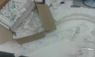
Having dismantled a corner section waiting for an software install last week, I attempted to remount the power rails into a track section of my own devising. The idea here is that we can reform the track and underlay to suit our own requirements (like adding space for wires or solar panels), make it slipperier (to make our AI look more professional), and increase the wow factor (by making it transparent, although this was a side effect of the acrylic sheet available today).

So a quick morning creating a CAD model (urgh, real objects ...) followed by a lengthier  afternoon with the laser cutter up in the engineering workshop, and I had my track section.

I do think that there will be future evolutions. The rails taken from the original scalextric track, while nice, are a pain to work with - I will try to come up with an alternative. Additionally I must have got my geometry wrong because the trusty file made several appearances!

On the other hand the track piece looks amazing, and could be made to be quite slippery. It also has lots of room for wires.

As you can see, it was only a mini piece.
Anyway, until next time!

Monday, 8 May 2017

The telescope continues...


Soooo - I may have built another telescope and not documented the process at all. Which is a bit of a problem as I now have a folder full of CAD files with really odd, but meaningful, names (like: "SlottyThings.ipt", why did my past self do this to me!). Luckily I have some nice work in progress photos, even if my in depth description may be a bit lacking.

The telescope is a 76mm Newtonian reflector with a potentially equatorial mount. The optical tube, and mount were built using the university laser cutter. Unfortunately I am not yet skilled enough to make the mirrors, mirror cell, tripod or eyepiece myself, so they had to be purchased/scrounged.

The optical tube with the two cheaty elements, the secondary holder and the primary cell. I like the fact that it looks like a big ray gun!

Tube clad in a sheet of black fabric to guard against light pollution, with two points of interest. One, the photo is from before the final mount was assembled so the telescope is attached straight onto the tripod. This was way too shakey and has not been done since. Additionally, you can see the £5 telescope in the bottom right corner! Safe to say the new telescope is incomparably better.

Drama shot, now with proper mount. There have been a couple of modifications since this photo to stiffen up the mount and tripod, but essentially the telescope still looks like this.


Of course no project would be complete without an even more ambitious project to follow it. Thus, "Operation Sandra Voi", the plan is to produce a mosaic image of the moon by stitching together lots of smaller images. My eyepiece's field of view is quite limited, so this is the only way I can produce a complete picture of the moon, and hopefully it will look really good when it is done: I can always go back and re-image sections that are either incomplete or of poor quality after a first pass.

"Sandra Voi" is named after one of the lighthuggers from Alastair Reynolds's Revelation Space series, only mentioned in passing a couple of times, it is an exploration ship just as hopefully the project will help me explore astronomy (ha ha, maybe I should have come up with a cool acronym instead). The naming scheme does leave me with a bit of a problem as I haven't thought of a cool enough project to call "Operation Nostalgia for Infinity" yet...


Photo, apologies for any confusion, due to the optics of the telescope the image is flipped, I also have no idea about the rotational orientation! I am fairly sure that it is the boundary between the Mare Serenitatis and Mare Imbrium, with a fairly faint Copernicus crater at the top of the image.

Preliminary mosaic with a nice template in the background kindly provided by good 'ol NASA.