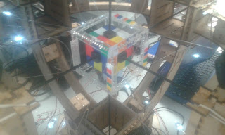
I suppose I should begin this post with an update on Gigaton Handshake: Optional Ultimatum (Giga to its friends). The last post saw the completion of the CAD design and I can happily report that is has now been built, wired, tester, rewired and is looking forward to its final tests/fixes a full two months before the next competition here at the uni. Does this mean that we are going to sit on our hands for a full two months waiting for action? Of course not, and unfortunately that means we shall start with a digression.
 |
| Gigaton Handshake |
Evil cat time, high backed chair slowly rotating... flash of lighting!
"MWAHAHAHA"
"Sit on our hands! Sit ... on ... our ... handssssss??"
As a project this has been rather interesting so far, it took us ages to come up with the correct design requirements but once we had them the rest of the design has gone quite well. We broke down our requirements as follows:
The board was determined to have to be able to:
The ESP32 device we chose had several major features that fixed most of these issues. Firstly it combined the transceiver and micro-controller and implemented all of the RF circuitry, making the PCB design much easier. It also has the ability to communicate via Bluetooth (classic and low energy). This means that we get a full communications stack given to us with all interactions happening at the application layer, much less of a headache than the PHY level interface the Si4463 was offering! Using Bluetooth also means that we can use the transceivers in our phones to communicate rather than having to build new hardware ... once we learn how to build Android applications ...
Back to Gigaton Handshake which went together fairly well, the uni's student workshop had some brilliant metal cutting tools for the front armour plate which meant I was able to cut a couple of spares, just in case. The 3D print went well, the new uni printers work like a dream. Initial construction was surprisingly painless (amazing how good things can get when you actually plan them) and only required one revision after initial testing.
The issue was, in true what-can-go-wrong style, electrical. When I had wired up the robot initially it had both the drive motors and radio receiver powered from a couple of power regulators on the brushless motor controller board. This worked really well until the motors tried to draw a lot of current, for example trying to turn really fast from a standstill. This drew all of the available current (about 3A) from the power regulators and starved the receiver, which promptly crashed. Luckily this was a problem with a quick fix and the motors are now powered directly from the battery, which has a larger possible current output of ~20A, before exploding.
The brushless motor works with relatively little fuss, the blade needed to be roughly balanced before I was happy using 100% throttle, this was done with a piece of string and a file.
This robot is now roughly finished, with only a couple of improvements. The first is to add the now distinctive drinks can blade to the front to increase scoopiness. The second will be to take a file to a couple of the edges to try and get the maximum dimensions down a bit. The third, possibly more important step will be to hot glue all of the components down to the chassis, with about 50g space weight I am hoping that I can use enough glue to almost act as impact softeners shielding the electronics from sharp blows when the robot is thrown about. The final step will be to upgrade the wheels.
Given I have lots of spare mass to play around with the wheels are going to be triple layered with alternating MDF and Perspex pieces. The idea is that putting MDF on the ends of the wheel will allow it to absorb spinner hits while the central perspex layer will provide a bit of rigidity. The final innovation is to add teeth to the outside of the wheel, these are not to grip the arena floor themselves, but to grip a layer of rubbery plastic that will be added later which should increase the wheel grip dramatically. Like all good 2D components these will be cut on the laser cutter at Uni.
- Be powered from a lithium polymer cell with an input voltage range of 3.5V to 14V to allow 1-3 cell li-po batteries to be used.
- Control 2 DC brushed motors directly with 2V/Vbatt continuous current draw
- Supply control signals and power to two servos with 200mA/5V current draw.
- Receive and process human commands into servo/motor outputs.
- Human must be remote from board (commands must be transmitted wirelessly)
- Wireless communication must be able to penetrate 5mm polycarbonate
- The board must have an interface to allow its firmware to be updated
- There were a bunch of size requirements too to ensure that we were actually getting an improvement with the new board.
The next step was to determine the system architecture and hardware that could realise these aims. Initially the plan was to use a discrete micro-controller, RF transceiver, motor controller, and power regulator however after much discussion we managed to address the functionality of the first two with an ESP32 board.
The selection of the ESP32 was quite an interesting process as initially we had lined up to use two chips, an ATMega328p micro-controller and Si4463 sub-GHz RF tranciever. Our reasoning was that the AtMega chip met all of our requirements and could be programmed with the Arduino bootloader, allowing us to use the Arduino IDE and libraries which makes the embedded code much easier to develop. Additionally the Si4463 was similar to the CC110Ls used during the Blake Project, and at sub 1-GHz we were going to run into RF weirdness during PCB design, but not too much.
My group member had got to a late stage in the PCB design before we swapped over to the ESP deivce, partially due to both our dawning horror at what the AtMega and Si4463 would require to get working. My group member was having serious concerns about the challenge in routing all of the signals between the two devices and to the transceiver's antenna while keeping to board to a reasonable size. I was having second thoughts having done some preliminary work designing a wireless protocol as an improvement on my naive effort during the Blake project (one specific improvement being not crashing whenever a single packet was lost). The work I had put together in preparation had already filled many sheets of paper with flow charts but I was still unsure of its effectiveness, or even its ability to be implemented. Finally both of us had realised that we were going to have issues with the Si4463 as we would need to create another device from scratch to allow a human to generate the RF transmissions.
The ESP32 device we chose had several major features that fixed most of these issues. Firstly it combined the transceiver and micro-controller and implemented all of the RF circuitry, making the PCB design much easier. It also has the ability to communicate via Bluetooth (classic and low energy). This means that we get a full communications stack given to us with all interactions happening at the application layer, much less of a headache than the PHY level interface the Si4463 was offering! Using Bluetooth also means that we can use the transceivers in our phones to communicate rather than having to build new hardware ... once we learn how to build Android applications ...
Gathering mist and darkness, spooky castle fades into the background, maniacal laughter slowly dying away...
The issue was, in true what-can-go-wrong style, electrical. When I had wired up the robot initially it had both the drive motors and radio receiver powered from a couple of power regulators on the brushless motor controller board. This worked really well until the motors tried to draw a lot of current, for example trying to turn really fast from a standstill. This drew all of the available current (about 3A) from the power regulators and starved the receiver, which promptly crashed. Luckily this was a problem with a quick fix and the motors are now powered directly from the battery, which has a larger possible current output of ~20A, before exploding.
The brushless motor works with relatively little fuss, the blade needed to be roughly balanced before I was happy using 100% throttle, this was done with a piece of string and a file.
 |
| Giga, a view of the other side a bit emptier as it usually holds the battery (which is currently staying in its lipo safe) |
Given I have lots of spare mass to play around with the wheels are going to be triple layered with alternating MDF and Perspex pieces. The idea is that putting MDF on the ends of the wheel will allow it to absorb spinner hits while the central perspex layer will provide a bit of rigidity. The final innovation is to add teeth to the outside of the wheel, these are not to grip the arena floor themselves, but to grip a layer of rubbery plastic that will be added later which should increase the wheel grip dramatically. Like all good 2D components these will be cut on the laser cutter at Uni.
 |
| Cad rendering of the wheel design, blue will be MDF, red will be perspex. |


