Friday, 16 February 2018

Rubik's Cube ... Sphere

Hooray! Images from the Rubik's Cube project!

After many days of hard work from the team I am in we have finally completed the chassis for the solver, which will hold the cube, actuators and any electronics required. The idea when designing this chassis was to make the actuator mounts (these are the large empty boxes) as flexible as possible - meaning that we can build and test other subsystems (like cameras) before the motors and gearboxes are ready.

A quick note, this is my EEE degree's third year group project. Seeing that we are third years the project supervisor has decided to make things slightly harder - all communication to the chassis mounted electronics (and motors) has to be done via an audio cable, and we are not allowed programmable devices to decode the information from the cable. The team's solution to this involves a PC soundcard, lots of bandpass filters and a couple of basic ADCs to implement a simple analogue shift keying communication scheme with multiple sub channels separated in the frequency domain. The lack of programmable logic has left us having to control the actuating servos with one-hot logic, which slows down our solving speed considerably.
The cube sphere!
Three years of Engineering education put to good use in finding a way to hold the cube in place for camera testing. (Hot glue was also used)


Tuesday, 13 February 2018

GrAVITAS - the circuit board

Ha! 
GrAVITAS returns - a bit worse for wear (having been stored in carbonite for so long). Work has finally got manageable enough for me to return to work on the solar flare detector. Actually, I lie - there were a couple of brilliant team members who persisted with their task, even when I went quiet on the subject, who galvanised me into action.

So, the progress:
1. Much software doings, it is only the scheduling and reporting that needs to be done. Having said that I have discovered (from other similar projects on the web) that NOAA publish the information from GOES-15's solar instruments, which would be brilliant to compare with the data we capture - and could be used entirely automatically.

2.I finally got around to the hardware, and have now planned out the analogue signal chain. Luckily due to the audio card digitising the signal, it does not have to be too complicated. A couple of buffers, amplifiers, a notch filter and a bandpass filter and everything is awesome! Needless to say, I expect the receiver to work terribly in this first iteration, but maybe by the fifth.... I think that while the design below does not include them I may end up adding a load of potentiometers in the place of some of the resistors to allow me to bodge optimise the circuit parameters!
My planned matrix board layout for the analogue signal chain. All go for soldering up on Thursday.
Hopefully I can post soon about even more progress, but I expect that my targets may slip - we have another Blake Project presentation opportunity this weekend which may eat a lot of time.

Wednesday, 31 January 2018

Focuser Complete

The focuser is complete!

Actually it has been complete for a week, but I have been too busy enjoying the sky to post about it.

Turns out that I am not yet genius enough to design something to work first time just yet: during construction there were some improvisations I had to make with the original design that I will go through below.

Now that the focuser is working the difference in viewing quality is enormous. Being able to get the focus exactly (okay, not quite exactly) right without shaking the entire scope, as my friction fit focuser did, means that I can get sharp images without the telescope moving itself away from a target.

This will hopefully mean that I can finally start using the telescope to the limit of my optics. This is a welcome change from the limiting factor being something that I have done (or not done!).

The focuser
The focuser still needs a bit of touching up, at the moment the axle bar is a threaded rod which can lead to interesting interactions with the securing bolt and tends to shred the eyepiece holder. It is also 1mm too thin - I am probably going to take a quick trip to the hardware store soon to find a replacement and solve these issues.

Additionally, I managed to find a PVC plumbing fitting that fitted my required dimensions, but now is acting as a brilliant reflector of stray light into the eyepiece - I am going to have to paint it black at some point.

Finally my method of attaching the focuser to the scope can be seen above, it is not very pretty, but works well enough, for now. At some point in the future I may get around to improving the mounting mechanism.

Shot straight through the eyepiece slot. One of the things that did work were the four bearings which, due to a combination of brilliant datasheets from RS and the precision of the laser cutter, are precisely where they need to be.

The revised fastening mechanism. It seems to work quite well.
 One of the things that changed dramatically was the fastening mechanism. I turned out that I had not left enough room for the spring in my design. Looking around the web at other homemade focusers revealed that a surprising number simply used a bolt pressing on the axle to secure it. This also solves the longer term problem of the spring wearing out as the spring is now provided by the structure, it also saves me a wing nut for use in future projects.
I have epoxied a nut on the axle side of the back plate to hold the bolt, with a cannibalised section of the original pusher plate used to provide extra counter-torque on the nut. One of the problems that has arisen from the threaded rod being used as an axle is that it likes to move left to right (up-down in the photo above) when it is turned while under pressure from the bolt. This is usually fine, but can be a surprising pain.

Mirror holder - modified!
The final modification was probably the scariest, and is likely going to require more work in the future. Because the new focuser is about 3cm taller that my old loo-roll eyepiece holder, I needed to shorten the tube of the telescope by about this amount to move the focal point of the mirror. By pure chance, when I had originally put the tube together I had made the main spars out of two shorter sections of wood bolted together. This meant that shortening the tube was a simple matter of swapping out the shorter of the two pieces with an even shorter piece (as seen in the photo above). I was a bit sad to say goodbye to some of the last remaining original and reliable components of the telescope.
Unfortunately, because he tube shortening only occurred at one end, and the current setup does not allow me to slide the mount attachment point around, this has thrown the balance of the telescope off. Even with the proper mount, the front of the telescope really wants to drop. While I could revert to the old method of hanging a bag of rice from the mirror cell, I think that the longer term solution is going to be rebuilding the telescope tube assembly as this will also allow me to incorporate some of the lessons I have learn't (like having a movable pivot point).

One quick project down, how many more to go?


Thursday, 18 January 2018

Telescope focuser

First post for the year is a surprise blast from the past: progress on the telescopes focuser - please try to hide that rolling of eyes.

So, almost a year after throwing the first bits of the telescope together I finally got into the mood to do some serious design work on the last major element of the telescope left - the eyepiece focuser.

Up until this point my eyepieces have been held in with friction and toilet rolls which is not to stable and does not allow for fine movements of the eyepiece. With the gradual upgrade in the other system components the focuser has finally become the weakest link.

A quick google search can show all sorts of brilliant designs - most of which have been made by someone else who is trying to sell them to you. Luckily there are also scattered articles of people making their own - generally with the a high level of ingenuity that most amateur telescope makers seem to possess by default.

In particular the ingenious Crayford focuser design, while used in high end commercial models, has been constructed in all sorts of ways including from assorted wood and plumbing scraps. That sounds like something I can do - especially when I have my trusty sidekick: Mr Laser-Cutter (its a double barrelled name).

I have just finished my CAD model ready for a workshop session sometime soon, which incidentally means I have pictures:

the focuser - note that my CAD skills are limited - I have not managed to put all my parts in an assembly to make the design look completely pretty.
The top view - hopefully the holes for the two bearing holders are visible on the left hand side of the image - the pressure will be applied with a spring pushing a pusher plate against the axle (which will happen on the right hand side of the image.

The pusher plate, I have tried to reduce its contact area with the rest of the focuser while maintaining its ability to stay straight by giving it the bowing in sides.


Monday, 27 November 2017

Blake Project: all power to the engines!!

Just a quick post,

The Blake Project is to be presented on Friday, all or nothing, do or die - this is the final push!!!

UPDATE:

It worked, it actually worked! We had a few final system integration issues which meant that the Radar was the only thing that was properly presentable, however this seemed to work for our audience who I don't think would have enjoyed the autonomous car as much.
In a flash of madness I had laser cut some props to use on the day which meant we ended up pretending we had Darth Vader stopping cars travelling too fast (we had a silhouette of him and it kind of made sense) - segueing into a discussion of the radar if we found someone who was interested.

We now have another set of dates to have the project ready for presentation on, hopefully with a bit more success.

Sunday, 19 November 2017

One small glued joint for a student, a great leap for the Blake Project!

The Blake Project progresses. With pictures!

Work has been steadily progressing on the perspex track over the past month or so, but the past week has seen some major progress (not least because all lectures were suspended for a reading week). Because it was never going to be any other way, the first full completion of the track occurred this evening, just before the term resumes again. 

Shiny completed perspex track! (just imagine that the electrical tape holding the different sections together is not there)
 Why is this a 'first' completion?

  1. There is some trouble with the spacing between the rails at a couple of points. Unfortunately fixing this will probably require replacing the perspex of one of the straight sections.
  2. As seen in the photos the only satisfactory way to keep the track sections together at the moment is to use electrical tape - which is counterproductive in terms of making the race track look awesome. Ideally I would be able to glue all the sections together into one really large track piece. This might make the track difficult to handle and store so I will need to consult with the rest of the project team...
  3. Some of the pylons need to be moved around as they have been attached randomly at the moment with no thought for where the ones with extra attachment points should be so that the speed traps can use them.
These issues have to be addressed soonish, we have been asked to complete the project for 6th December by our supervisors, and many of the other project elements are now waiting on the track to be finished before they can start proper testing.

Therefore there is almost certainly going to be a 'victory' post in the near future! 

Until then ...

Atmosphere shot, same as when only the first two sections were complete, but now with the whole track!!

Hmm, I was going for more atmosphere - being able to see the top track from below - but all I can see is the mess of loose wires!

Thursday, 16 November 2017

When your problem is life ... and that infinitely repeating operation you programmed months ago

All right all right, I am the first to admit that in the grand scheme of things my programming ability is only slightly higher than that of a large twig.

However, my programs, in particular the growing gargantuan that is the Blake Project wireless network base station and autonomous car coordinator, do get to do some cool stuff.

The coolest of these is using my computer's full capacity. There is a certain joy in writing a program that takes so long to run that you can have a cup of tea while it executes ... if you ignore the fact that it is only relatively recently that this has stopped being a common occurrence, and that most of the delay is due to your inefficiency anyway. The Blake Project base station is a prime example of this pride's initial warm glow swiftly followed by agonising pain of n-degree noob programming burns.

In order to service both a GUI and several external serial links the base station implements multi-threading, executing multiple scripts 'at once' (not really it just fills in all the empty space that usually fills up a single thread of execution). While it means I get to use fancy terms like 'concurrent processing' when describing system behaviour, all this filling of idle operations also means that the CPU utilisation can get fairly high as well.

Unfortunately it got slightly too high as seen below, and the program started to lag.
Multithreading in python is only able to use a single processor core. We can see it maxing out the leftmost core until I swiftly kill it.
The primary reason for this was that one of the older threads had been allowed to request access to shared resources a quickly as it liked. This is BAD news, because it can ask as often as it wants (or can - if we have to insist that computers are inanimate), not getting the resource shortens the time the thread does other stuff for before asking again because what it was going to to do relies on the resource being given to it. Think annoying 'are we there yet' questions which are incessant until the answer is 'yes'.

The spoilt child analogy naturally develops when the thread's response to actually getting the resource is to look at it, see that nothing has changed since last time it looked (the data it was looking for only came through every now and then), and thus immediatly close the resource and release it for others to use.

Only to immediately ask for it back.

The solution is to teach everyone some manners, introducing delays into the loops of which the loops are a part, and re-enabling 'blocking' of the requests (pausing the program until it is successful, which reduces the number of requests enormously - there were good reasons for me disabling this I promise). This is going to have knock on effects later on which may or may not be irrecoverable, luckily that is for future me to work out.

Threads with manners, now using the CPU cores in a much more respectable manner. I don't actually know which one it is running on!
In fact, there is a large chance that that is what my next post shall be about, we'll have to see!

Tuesday, 14 November 2017

An Update

Silence for months must be followed with an update post, it is a rule of nature.

At the beginning of the (academic) year I listed some of the projects that I am working on at the moment. Question: how are they going? Answer: ummmmmmmmmm - I'll get back to you.

Immediately.

Blake Project:

Turns out not spending eight hours a day on a project can really slow progress. The AI has been semi constructed, the algorithm has been written, and so has the car driving code. All that remains is to plug it all together (which is always the longest part anyway!).

The track, is in pieces. Not as many pieces as it was, but it is many hours from completion. Luckily we have a reading week at the moment with many hours in it, many fingers are being crossed.

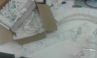
Its all there! Just not together.

 Telescope:

The updates that need doing have been identified, I really need to install a focussing mechanism better than a loo roll and friction. Also, upgrading the optical tube frame to be more portable, yet sturdier, is definitely on the cards at some point.

The telescope has had some good outings recently, trying but failing to see Uranus, getting a peek at Mars and a good look at the Orion nebula. I was going to try and point it at Jupiter and Venus on Tuesday, but the only place I could see them was from the middle of a road (I live in a city and they were close to the horizon), which I did not think was appropriate. They were awesome enough with the naked eye!

Solar Flare Detector:

Designed, the project decided to change the receiver to an SDR (software defined radio) based one, plugging the antenna (after a couple of filters and amplifiers) into a microphone slot and using a computer to do all the hard work. As it should.

Of course given that the solar flare detector should be running fairly constantly we have elected to use a Raspberry Pi as our enslaved processor - which means I have to relearn linux.

Also it got a name the GRand Assembly for Versatile Ionosphere Tracking and Astronomy of the Sun or GrAVITAS, a ripe source of puns, a source of gravitas (can't help myself), and of course an oblique reference to Iain M Banks. It looks very good in email headers.
The engineer at work, all four monitors in use. More screens = more work being done right?

Rubik's Cube Solver:

Good progress, but nothing of note yet. At least nothing worthy of photographing!


Lunar Rover Mk2:


Wow - got assigned to other projects within the space society for the moment, which was rather unexpected. The sneaky plan of the committee is to shuffle members around between projects as work amounts change. Ideally this means that some point in the future there will be much posting about rovers, the ideas coming out of the rover team so far are really rather cool.

Random Shiny stuff:

It always happens.

Robot Wars.

So the university electronics society run an ant-weight (150g, 10cm cube size limit) competition twice a year, so I should have seen this coming. Because this is going to be the fifth time we have entered, my team is going to attempt to build a cluster-bot, fitting multiple independent robots within the restrictions. This is leading to all sorts of fun and games trying to reduce the mass of the individual components of the robots which is likely to be the tricky bit.

This one also has a name, The Rock and a Hard Plaice, more details to come soon.

Who needs scales when you have string, water and a measuring jug?

Friday, 20 October 2017

An act of frequency folly

Working through some software problems today ended in some rather funny solutions this morning (why do programming breakthroughs always seem to happen when everyone else is asleep??).

It just so happens that both the Rubik's Cube Solver and the Solar Flare Detector are going to require me to become a pro at manipulating PC soundcards, both for sending and receiving signals.

Sending signals is fine:

    1. Find a nice stable interface library, 
    2. Bash together some sample values,
    3. Send them off to generic 'write' function,
    4. Play sweet sweet music,
    5. Become single most hated person in the lab for constantly playing annoyingly pitched sine tones...
Receiving signals is proving slightly trickier, or rather analysing the received signals in the frequency domain is proving rather mind bending. To illustrate, some nice graphs:
An arbitrary signal received through my PC's microphone (in the time domain). Ignore both axis for the moment.
The reported amplitude spectrum of the above signal. The fact that is is clearly just a copy of the original signal put through an 'magnitude' function rang many alarm bells. Another bell ringer was the fact that is not symmetrical around the Nyquist frequency (~22 kHz), a necessary outcome of an FFT. We can read the bottom axis as frequency directly.
An example of what I was expecting to see, a nicely prepared amplitude spectra of two superimposed sinusoids with a large DC offset. We can use the bottom axis as frequency again. Note that it ends at about 22 kHz, the magics of digital sampling mean that anything above this frequency is simply a reflection of the spectra below that point - it is easier to not show it.
What appeared to be happening was that the Fast Fourier Transform (FFT) function I was using seemed to like synthesised, simple, waveforms - but not horrible real life ones.

At this point it is probably a good idea to give some indication of the software I am using, as it turned out my interpretation of it was the cause of most of my errors. In general when programming on a PC or large computer I like to use Python 3, and for this particular task I deployed the potent Numpy/Matlibplot library combo. Initially I was using PyAudio to interact with sound related hardware, but I quickly realised that the sounds it was producing were awfully messy and did not correspond to the carefully crafted sine waves I was trying to generate. After digging around and seeing some other people complaining on various forums I switched to the SoundDevice library which promised to be more stable. It was, and I quickly progressed from producing signals to trying to receive them.

That was when I started producing graphs like those above. I dug around, maybe my received data needed to be in another format ... maybe I needed to change the sampling frequencies ... e.c.t. (That last 'solution' turned out to be an incredibly bad idea, I can only guess that the software  and hardware supporting the soundcard and Python interface is optimised for specific sampling rates, because who would want to change that? :) )

Several hours of digital sampling theory, frequent code double checking and desperate internet searches ended when I realised that I had misunderstood some documentation and got my rows and columns mixed up when feeding data to the FFT function.

As quickly as I realised my problem all anger at my poor computer subsided, I had been asking it to compute the frequency content of thousands of individual samples (which gives the amplitude of said samples at DC/0 Hz) and then plot the results. Instead of plotting a bunch of data points at x = 0, Python had plotted each individual result like a column graph which (unsurprisingly) produced a copy of the original signal with all negative results flipped to be positive. The reason the synthesised waveform had not had this problem was because it was stored differently and so did not have its rows and columns confused.

Once I started using the data correctly my issues quickly resolved and I began producing graphs like the one below, cheering and waking up all my flatmates...
A nicer frequency amplitude spectrum of the signal incorrectly processed above. It has had its spectra cut off around 22 kHz in the same manner as the spectra of the synthesised signal. I am fairly sure that everyone in my terrace of houses knows I was able to produce this graph. 
Sorry that this has been a bit of a dry post, I have to take the opportunity to write when something happens that is both applicable, and has shiny images!

Anyway, until next time....

New academic year == new projects

Another year of Uni has now begun, with the promise of a number of awesome projects to work on. This is not to say that the current work is going to be dropped, the Blake project in particular is continuing with the deadline of being complete by June next year.

However, the excitement always lies with the shiny new projects with all of the potential and none of the pragmatism (yet):

Being on the committee for the university's space society has meant that I was hoping to be able to push some electronics into the normal roster of rocket and rover projects. This push has resulted in the Solar Flare Detector being adopted as a project for this year. Consisting of a VLF radio receiver the end product will be able to track the sudden ionospheric disturbances that usually accompany flares hitting the Earth. Before you go and talk about us heading towards a solar minimum at the moment, which we are, there are still flares to be detected - just slightly smaller and less frequent flares. This project is currently starting up and already providing interest in the society from a broader range of subject disciplines, beyond the usual Aerospace Engineers.

The society is also re-entering the UKSEDS lunar rover competition after our successes last year (we came second), hoping to build on our design which ended up being decidedly improvised towards the end. It is likely the electronics are going to get a major overhaul but this should not be too hard given we now have experience.

Finally (for the moment) being the third year of the degree part of the assessment this year involves a group project. The aim of this project will be to produce a machine capable of solving a Rubik's cube. There are several restrictions that are going to add cool (and not obvious) electronics - I am sure that these will turn up in a future post.

Ongoing projects include the brilliant Blake Project, now cruising to completion - some sneakery is going to allow the accelerometer problem to be sidestepped, again I am sure that this will be written about somewhere else. The track itself is also slowly being completed - the workshop restocked perspex for the new term, and I immediately helped myself and spent a happy couple of hours producing all the parts needed.

At an even slower pace is the telescope, dredged from the depths of the blog. While I have really enjoyed using it so far there have been certain areas that either need improving or have already been improved. The mount (both tripod and pivot) have both been replaced with far more capable, but sadly not quite as DIY-y, elements. My range of eyepieces has also increased beyond a single dodgy 7.5mm plossl. Using the new setup I can clearly see all four stars in Mizar/Alcor, some awesome detail on the moon, the rings of Saturn e.c.t. However there is still more to do, I would like to 3D print an eyepiece holder and at some point I am going to need to replace the current optical tube frame.

All good things to look forward to, an hopefully write about!

A Summary:

Ongoing Projects:
    1. Blake Project (at a slower speed during the academic year)
    2. Telescope (gradually improving portability and stability)
New Projects:
    1. Solar Flare Detector (cooler acronym incoming)
    2. Rubik's Cube Solver (for degree)
    3. Lunar Rover Mk. 2.